Optics is the branch of physics which involves the behavior and properties of light, including its interactions with matter and the construction of instruments that use or detect it. Optics usually describes the behavior of visible, ultraviolet, and infrared light. Because light is an electromagnetic wave, other forms of electromagnetic radiation such as X-rays, microwaves, and radio waves exhibit similar properties.
Most optical phenomena can be accounted for using the classical electromagnetic description of light. Complete electromagnetic descriptions of light are, however, often difficult to apply in practice. Practical optics is usually done using simplified models. The most common of these, geometric optics, treats light as a collection of rays that travel in straight lines and bend when they pass through or reflect from surfaces. Physical optics is a more comprehensive model of light, which includes wave effects such as diffraction and interference that cannot be accounted for in geometric optics. Historically, the ray-based model of light was developed first, followed by the wave model of light. Progress in electromagnetic theory in the 19th century led to the discovery that light waves were in fact electromagnetic radiation.
Some phenomena depend on the fact that light has both wave-like and particle-like properties. Explanation of these effects requires quantum mechanics. When considering light's particle-like properties, the light is modeled as a collection of particles called "photons". Quantum optics deals with the application of quantum mechanics to optical systems.
Optical science is relevant to and studied in many related disciplines including astronomy, various engineering fields, photography, and medicine (particularly ophthalmology and optometry). Practical applications of optics are found in a variety of technologies and everyday objects, including mirrors, lenses, telescopes, microscopes, lasers, and fiber optics.
History
See also: Timeline of electromagnetism and classical optics
Optics began with the development of lenses by the ancient Egyptians and Mesopotamians. The earliest known lenses were made from polished crystal, often quartz, and have been dated as early as 700 BC for Assyrian lenses such as the Layard/Nimrud lens. The ancient Romans and Greeks filled glass spheres with water to make lenses. These practical developments were followed by the development of theories of light and vision by ancient Greek and Indian philosophers, and the development of geometrical optics in the Greco-Roman world. The word optics comes from the ancient Greek word ὀπτική, meaning appearance or look. Plato first articulated emission theory, the idea that visual perception is accomplished by rays emitted by the eyes. He also commented on the parity reversal of mirrors in Timaeus. Some hundred years later, Euclid wrote a treatise entitled Optics wherein he described the mathematical rules of perspective and describes the effects of refraction qualitatively. Ptolemy, in his treatise Optics, summarizes much of Euclid and goes on to describe a way to measure the angle of refraction, though he failed to notice the empirical relationship between it and the angle of incidence.
During the Middle Ages, Greek ideas about optics were resurrected and extended by writers in the Muslim world. One of the earliest of these was Al-Kindi (c. 801–73). In 984, the Persian mathematician Ibn Sahl wrote the treatise "On burning mirrors and lenses", correctly describing a law of refraction equivalent to Snell's law. He used this law to compute optimum shapes for lenses and curved mirrors. In the early 11th century, Alhazen (Ibn al-Haytham) wrote his Book of Optics, which documented the then-current understanding of vision.
In the 13th century, Roger Bacon used parts of glass spheres as magnifying glasses, and discovered that light reflects from objects rather than being released from them. In Italy, around 1284, Salvino D'Armate invented the first wearable eyeglasses.
The earliest known telescopes were refracting telescopes, a type which relies entirely on lenses for magnification. The first rudimentary telescopes were developed independently in the 1570s and 1580s by Leonard Digges, and Giambattista della Porta. Their development in the Netherlands in 1608 was by three individuals: Hans Lippershey and Zacharias Janssen, who were spectacle makers in Middelburg, and Jacob Metius of Alkmaar. In Italy, Galileo greatly improved upon these designs the following year. In 1668, Isaac Newton constructed the first practical reflecting telescope, which bears his name, the Newtonian reflector.
The first microscope was made around 1595, also in Middelburg. Three different eyeglass makers have been given credit for the invention: Lippershey, Janssen, and his father, Hans. The coining of the name "microscope" has been credited to Giovanni Faber, who gave that name to Galileo's compound microscope in 1625.

Cover of the first edition of Newton's Opticks
Optical theory progressed in the mid-17th century with treatises written by philosopher René Descartes, which explained a variety of optical phenomena including reflection and refraction by assuming that light was emitted by objects which produced it. This differed substantively from the ancient Greek emission theory. In the late 1660s and early 1670s, Newton expanded Descartes' ideas into a corpuscle theory of light, famously showing that white light, instead of being a unique color, was really a composite of different colors that can be separated into a spectrum with a prism. In 1690, Christian Huygens proposed a wave theory for light based on suggestions that had been made by Robert Hooke in 1664. Hooke himself publicly criticized Newton's theories of light and the feud between the two lasted until Hooke's death. In 1704, Newton published Opticks and, at the time, partly because of his success in other areas of physics, he was generally considered to be the victor in the debate over the nature of light.
Newtonian optics was generally accepted until the early 19th century when Thomas Young and Augustin-Jean Fresnel conducted experiments on the interference of light that firmly established light's wave nature. Young's famous double slit experiment showed that light followed the law of superposition, which is a wave-like property not predicted by Newton's corpuscle theory. This work led to a theory of diffraction for light and opened an entire area of study in physical optics. Wave optics was successfully unified with electromagnetic theory by James Clerk Maxwell in the 1860s.
The next development in optical theory came in 1899 when Max Planck correctly modeled blackbody radiation by assuming that the exchange of energy between light and matter only occurred in discrete amounts he called quanta. In 1905, Albert Einstein published the theory of the photoelectric effect that firmly established the quantization of light itself. In 1913, Niels Bohr showed that atoms could only emit discrete amounts of energy, thus explaining the discrete lines seen in emission and absorption spectra. The understanding of the interaction between light and matter, which followed from these developments, not only formed the basis of quantum optics but also was crucial for the development of quantum mechanics as a whole. The ultimate culmination was the theory of quantum electrodynamics, which explains all optics and electromagnetic processes in general as being the result of the exchange of real and virtual photons.
Quantum optics gained practical importance with the invention of the maser in 1953 and the laser in 1960.Following the work of Paul Dirac in quantum field theory, George Sudarshan, Roy J. Glauber, and Leonard Mandel applied quantum theory to the electromagnetic field in the 1950s and 1960s to gain a more detailed understanding of photodetection and the statistics of light.
Classical optics

where v is the speed, λ is the wavelength and f is the frequency. Because the frequency is fixed, a change in the wave's speed produces a change in its wavelength.The speed of light in a medium is typically characterized by theindex of refraction, n, which is the ratio of the speed of light in vacuum, c, to the speed in the medium: - n = c / v.
The speed of light in vacuum is a constant, which is exactly 299,792,458 metres per second. Thus, a light ray with a wavelength of λ in a vacuum will have a wavelength of λ / n in a material with index of refraction n. The amplitude of the light wave is related to the intensity of the light, which is related to the energy stored in the wave's electric and magnetic fields. Traditional optics is divided into two main branches: geometrical optics and physical optics.
Geometrical optics

As a light wave travels through space, it oscillates in amplitude. In this image, each maximum amplitude crest is marked with a plane to illustrate the wavefront. The ray is the arrow perpendicularparallel surfaces. to these Geometrical optics, or ray optics, describes light propagation in terms of "rays". The "ray" in geometric optics is an abstraction, or "instrument", that can be used to predict the path of light. A light ray is a ray that is perpendicular to the light's wavefronts (and therefore collinear with the wave vector). Light rays bend at the interface between two dissimilar media and may be curved in a medium in which the refractive index changes. Geometrical optics provides rules for propagating these rays through an optical system, which indicates how the actual wavefront will propagate. This is a significant simplification of optics that fails to account for optical effects such as diffraction and polarization. It is a good approximation, however, when the wavelength is very small compared with the size of structures with which the light interacts. Geometric optics can be used to describe the geometrical aspects of imaging, including optical aberrations. A slightly more rigorous definition of a light ray follows from Fermat's principle which states that the path taken between two points by a ray of light is the path that can be traversed in the least time. Approximations
Geometrical optics is often simplified by making the paraxial approximation, or "small angle approximation." The mathematical behavior then becomes linear, allowing optical components and systems to be described by simple matrices. This leads to the techniques of Gaussian optics and paraxial ray tracing, which are used to find basic properties of optical systems, such as approximate image and object positions and magnifications. Reflections

Diagram of specular reflection
Reflections can be divided into two types: specular reflection and diffuse reflection. Specular reflection describes glossy surfaces such as mirrors, which reflect light in a simple, predictable way. This allows for production of reflected images that can be associated with an actual (real) or extrapolated (virtual) location in space. Diffuse reflection describes matte surfaces, such as paper or rock. The reflections from these surfaces can only be described statistically, with the exact distribution of the reflected light depending on the microscopic structure of the surface. Many diffuse reflectors are described or can be approximated by Lambert's cosine law, which describes surfaces that have equal luminance when viewed from any angle. In specular reflection, the direction of the reflected ray is determined by the angle the incident ray makes with the surface normal, a line perpendicular to the surface at the point where the ray hits. The incident and reflected rays lie in a single plane, and the angle between the reflected ray and the surface normal is the same as that between the incident ray and the normal. This is known as the Law of Reflection. For flat mirrors, the law of reflection implies that images of objects are upright and the same distance behind the mirror as the objects are in front of the mirror. The image size is the same as the object size. (The magnification of a flat mirror is unity.) The law also implies that mirror images are parity inverted, which we perceive as a left-right inversion. Images formed from reflection in two (or any even number of) mirrors are not parity inverted. Corner reflectors retroreflect light, producing reflected rays that travel back in the direction from which the incident rays came. Mirrors with curved surfaces can be modeled by ray-tracing and using the law of reflection at each point on the surface. For mirrors with parabolic surfaces, parallel rays incident on the mirror produce reflected rays that converge at a common focus. Other curved surfaces may also focus light, but with aberrations due to the diverging shape causing the focus to be smeared out in space. In particular, spherical mirrors exhibit spherical aberration. Curved mirrors can form images with magnification greater than or less than one, and the magnification can be negative, indicating that the image is inverted. An upright image formed by reflection in a mirror is always virtual, while an inverted image is real and can be projected onto a screen. [edit] Refractions
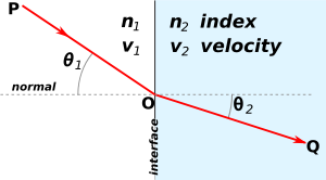
Illustration of Snell's Law for the case n1 < n2, such as air/water interface Refraction occurs when light travels through an area of space that has a changing index of refraction; this principle allows for lenses and the focusing of light. The simplest case of refraction occurs when there is an interface between a uniform medium with index of refraction n1 and another medium with index of refraction n2. In such situations, Snell's Law describes the resulting deflection of the light ray: 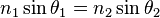
where θ1 and θ2 are the angles between the normal (to the interface) and the incident and refracted waves, respectively. This phenomenon is also associated with a changing speed of light as seen from the definition of index of refraction provided above which implies:

where v1 and v2 are the wave velocities through the respective media. Various consequences of Snell's Law include the fact that for light rays traveling from a material with a high index of refraction to a material with a low index of refraction, it is possible for the interaction with the interface to result in zero transmission. This phenomenon is called total internal reflection and allows for fiber optics technology. As light signals travel down a fiber optic cable, it undergoes total internal reflection allowing for essentially no light lost over the length of the cable. It is also possible to produce polarized light rays using a combination of reflection and refraction: When a refracted ray and the reflected ray form a right angle, the reflected ray has the property of "plane polarization". The angle of incidence required for such a scenario is known as Brewster's angle. Snell's Law can be used to predict the deflection of light rays as they pass through "linear media" as long as the indexes of refraction and the geometry of the media are known. For example, the propagation of light through a prism results in the light ray being deflected depending on the shape and orientation of the prism. Additionally, since different frequencies of light have slightly different indexes of refraction in most materials, refraction can be used to produce dispersion spectra that appear as rainbows. The discovery of this phenomenon when passing light through a prism is famously attributed to Isaac Newton. Some media have an index of refraction which varies gradually with position and, thus, light rays curve through the medium rather than travel in straight lines. This effect is what is responsible for mirages seen on hot days where the changing index of refraction of the air causes the light rays to bend creating the appearance of specular reflections in the distance (as if on the surface of a pool of water). Material that has a varying index of refraction is called a gradient-index (GRIN) material and has many useful properties used in modern optical scanning technologies including photocopiers and scanners. The phenomenon is studied in the field of gradient-index optics. 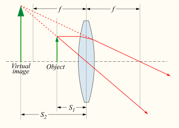
A ray tracing diagram for a converging lens. A device which produces converging or diverging light rays due to refraction is known as a lens. Thin lenses produce focal points on either side that can be modeled using the lensmaker's equation. In general, two types of lenses exist: convex lenses, which cause parallel light rays to converge, and concave lenses, which cause parallel light rays to diverge. The detailed prediction of how images are produced by these lenses can be made using ray-tracing similar to curved mirrors. Similarly to curved mirrors, thin lenses follow a simple equation that determines the location of the images given a particular focal length (f) and object distance (S1): 
where S2 is the distance associated with the image and is considered by convention to be negative if on the same side of the lens as the object and positive if on the opposite side of the lens. The focal length f is considered negative for concave lenses. Incoming parallel rays are focused by a convex lens into an inverted real image one focal length from the lens, on the far side of the lens. Rays from an object at finite distance are focused further from the lens than the focal distance; the closer the object is to the lens, the further the image is from the lens. With concave lenses, incoming parallel rays diverge after going through the lens, in such a way that they seem to have originated at an upright virtual image one focal length from the lens, on the same side of the lens that the parallel rays are approaching on. Rays from an object at finite distance are associated with a virtual image that is closer to the lens than the focal length, and on the same side of the lens as the object. The closer the object is to the lens, the closer the virtual image is to the lens.
Likewise, the magnification of a lens is given by

where the negative sign is given, by convention, to indicate an upright object for positive values and an inverted object for negative values. Similar to mirrors, upright images produced by single lenses are virtual while inverted images are real. Lenses suffer from aberrations that distort images and focal points. These are due to both to geometrical imperfections and due to the changing index of refraction for different wavelengths of light (chromatic aberration). Physical optics
Physical optics or wave optics builds on Huygens's principle, which states that every point on an advancing wavefront is the center of a new disturbance. When combined with the superposition principle, this explains how optical phenomena are manifested when there are multiple sources or obstructions that are spaced at distances similar to the wavelength of the light. Complex models based on physical optics can account for the propagation of any wavefront through an optical system, including predicting the wavelength, amplitude, and phase of the wave.Additionally, all of the results from geometrical optics can be recovered using the techniques of Fourier optics which apply many of the same mathematical and analytical techniques used in acoustic engineering and signal processing. Using numerical modeling on a computer, optical scientists can simulate the propagation of light and account for most diffraction, interference, and polarization effects. Such simulations typically still rely on approximations, however, so this is not a full electromagnetic wave theory model of the propagation of light. Such a full model is computationally demanding and is normally only used to solve small-scale problems that require extraordinary accuracy. Gaussian beam propagation is a simple paraxial physical optics model for the propagation of coherent radiation such as laser beams. This technique partially accounts for diffraction, allowing accurate calculations of the rate at which a laser beam expands with distance, and the minimum size to which the beam can be focused. Gaussian beam propagation thus bridges the gap between geometric and physical optics Superposition and interference
In the absence of nonlinear effects, the superposition principle can be used to predict the shape of interacting waveforms through the simple addition of the disturbances. This interaction of waves to produce a resulting pattern is generally termed "interference" and can result in a variety of outcomes. If two waves of the same wavelength and frequency are in phase, both the wave crests and wave troughs align. This results in constructive interference and an increase in the amplitude of the wave, which for light is associated with a brightening of the waveform in that location. Alternatively, if the two waves of the same wavelength and frequency are out of phase, then the wave crests will align with wave troughs and vice-versa. This results in destructive interference and a decrease in the amplitude of the wave, which for light is associated with a dimming of the waveform at that location. See below for an illustration of this effect.
combined
waveform |  |
| wave 1 |
| wave 2 |
| Two waves in phase | Two waves 180° out
of phase |

When oil or fuel is spilled, colorful patterns are formed by thin-film interference. Since Huygens's principle states that every point of a wavefront is associated with the production of a new disturbance, it is possible for a wavefront to interfere with itself constructively or destructively at different locations producing bright and dark fringes in regular and predictable patterns.Interferometry is the science of measuring these patterns, usually as a means of making precise determinations of distances or angular resolutions.The Michelson interferometer was a famous instrument which used interference effects to accurately measure the speed of light. The appearance of thin films and coatings is directly affected by interference effects. Antireflective coatings use destructive interference to reduce the reflectivity of the surfaces they coat, and can be used to minimize glare and unwanted reflections. The simplest case is a single layer with thickness one-fourth the wavelength of incident light. The reflected wave from the top of the film and the reflected wave from the film/material interface are then exactly 180° out of phase, causing destructive interference. The waves are only exactly out of phase for one wavelength, which would typically be chosen to be near the center of the visible spectrum, around 550 nm. More complex designs using multiple layers can achieve low reflectivity over a broad band, or extremely low reflectivity at a single wavelength. Constructive interference in thin films can create strong reflection of light in a range of wavelengths, which can be narrow or broad depending on the design of the coating. These films are used to make dielectric mirrors, interference filters, heat reflectors, and filters for color separation in color television cameras. This interference effect is also what causes the colorful rainbow patterns seen in oil slicks. Diffraction and optical resolution

Diffraction on two slits separated by distance d. The bright fringes occur along lines where black lines intersect with black lines and white lines intersect with white lines. These fringes are separated by angle θ and are numbered as order n. Diffraction is the process by which light interference is most commonly observed. The effect was first described in 1665 by Francesco Maria Grimaldi, who also coined the term from the Latin diffringere, 'to break into pieces'. Later that century, Robert Hooke and Isaac Newton also described phenomena now known to be diffraction in Newton's rings while James Gregory recorded his observations of diffraction patterns from bird feathers. The first physical optics model of diffraction that relied on Huygens' Principle was developed in 1803 by Thomas Young in his accounts of the interference patterns of two closely spaced slits. Young showed that his results could only be explained if the two slits acted as two unique sources of waves rather than corpuscles. In 1815 and 1818, Augustin-Jean Fresnel firmly established the mathematics of how wave interference can account for diffraction. The simplest physical models of diffraction use equations that describe the angular separation of light and dark fringes due to light of a particular wavelength (λ). In general, the equation takes the form
- mλ = dsinθ
where d is the separation between two wavefront sources (in the case of Young's experiments, it was two slits), θ is the angular separation between the central fringe and the mth order fringe, where the central maximum is m = 0. This equation is modified slightly to take into account a variety of situations such as diffraction through a single gap, diffraction through multiple slits, or diffraction through a diffraction grating that contains a large number of slits at equal spacing. More complicated models of diffraction require working with the mathematics of Fresnel or Fraunhofer diffraction. X-ray diffraction makes use of the fact that atoms in a crystal have regular spacing at distances that are on the order of one angstrom. To see diffraction patterns, x-rays with similar wavelengths to that spacing are passed through the crystal. Since crystals are three-dimensional objects rather than two-dimensional gratings, the associated diffraction pattern varies in two directions according to Bragg reflection, with the associated bright spots occurring in unique patterns and d being twice the spacing between atoms.Dffraction effects limit the ability for an optical detector to optically resolve separate light sources. In general, light that is passing through an aperture will experience diffraction and the best images that can be created (as described in diffraction-limited optics) appear as a central spot with surrounding bright rings, separated by dark nulls; this pattern is known as an Airy pattern, and the central bright lobe as an Airy disk.The size of such a disk is given by 
where θ is the angular resolution, λ is the wavelength of the light, and D is the diameter of the lens aperture. If the angular separation of the two points is significantly less than the Airy disk angular radius, then the two points cannot be resolved in the image, but if their angular separation is much greater than this, distinct images of the two points are formed and they can therefore be resolved. Rayleigh defined the somewhat arbitrary "Rayleigh criterion" that two points whose angular separation is equal to the Airy disk radius (measured to first null, that is, to the first place where no light is seen) can be considered to be resolved. It can be seen that the greater the diameter of the lens or its aperture, the finer the resolution. Interferometry, with its ability to mimic extremely large baseline apertures, allows for the greatest angular resolution possible. For astronomical imaging, the atmosphere prevents optimal resolution from being achieved in the visible spectrum due to the atmospheric scattering and dispersion which cause stars to twinkle. Astronomers refer to this effect as the quality of astronomical seeing. Techniques known as adaptive optics have been utilized to eliminate the atmospheric disruption of images and achieve results that approach the diffraction limit. Dispersion and scattering

Conceptual animation of light dispersion through a prism. High frequency (blue) light is deflected the most, and low frequency (red) the least. Refractive processes take place in the physical optics limit, where the wavelength of light is similar to other distances, as a kind of scattering. The simplest type of scattering is Thomson scattering which occurs when electromagnetic waves are deflected by single particles. In the limit of Thompson scattering, in which the wavelike nature of light is evident, light is dispersed independent of the frequency, in contrast to Compton scattering which is frequency-dependent and strictly a quantum mechanical process, involving the nature of light as particles. In a statistical sense, elastic scattering of light by numerous particles much smaller than the wavelength of the light is a process known as Rayleigh scattering while the similar process for scattering by particles that are similar or larger in wavelength is known as Mie scattering with the Tyndall effect being a commonly observed result. A small proportion of light scattering from atoms or molecules may undergo Raman scattering, wherein the frequency changes due to excitation of the atoms and molecules. Brillouin scattering occurs when the frequency of light changes due to local changes with time and movements of a dense material. Dispersion occurs when different frequencies of light have different phase velocities, due either to material properties (material dispersion) or to the geometry of an optical waveguide (waveguide dispersion). The most familiar form of dispersion is a decrease in index of refraction with increasing wavelength, which is seen in most transparent materials. This is called "normal dispersion". It occurs in all dielectric materials, in wavelength ranges where the material does not absorb light. In wavelength ranges where a medium has significant absorption, the index of refraction can increase with wavelength. This is called "anomalous dispersion". The separation of colors by a prism is an example of normal dispersion. At the surfaces of the prism, Snell's law predicts that light incident at an angle θ to the normal will be refracted at an angle arcsin(sin (θ) / n) . Thus, blue light, with its higher refractive index, is bent more strongly than red light, resulting in the well-known rainbow pattern. 
Dispersion: two sinusoids propagating at different speeds make a moving interference pattern. The red dot moves with the phase velocity, and the green dots propagate with the group velocity. In this case, the phase velocity is twice the group velocity. The red dot overtakes two green dots, when moving from the left to the right of the figure. In effect, the individual waves (which travel with the phase velocity) escape from the wave packet (which travels with the group velocity). Material dispersion is often characterized by the Abbe number, which gives a simple measure of dispersion based on the index of refraction at three specific wavelengths. Waveguide dispersion is dependent on the propagation constant. Both kinds of dispersion cause changes in the group characteristics of the wave, the features of the wave packet that change with the same frequency as the amplitude of the electromagnetic wave. "Group velocity dispersion" manifests as a spreading-out of the signal "envelope" of the radiation and can be quantified with a group dispersion delay parameter: 
where vg is the group velocity. For a uniform medium, the group velocity is

where n is the index of refraction and c is the speed of light in a vacuum. This gives a simpler form for the dispersion delay parameter: 
If D is less than zero, the medium is said to have positive dispersion or normal dispersion. If D is greater than zero, the medium has negative dispersion. If a light pulse is propagated through a normally dispersive medium, the result is the higher frequency components slow down more than the lower frequency components. The pulse therefore becomes positively chirped, or up-chirped, increasing in frequency with time. This causes the spectrum coming out of a prism to appear with red light the least refracted and blue/violet light the most refracted. Conversely, if a pulse travels through an anomalously (negatively) dispersive medium, high frequency components travel faster than the lower ones, and the pulse becomes negatively chirped, or down-chirped, decreasing in frequency with time.The result of group velocity dispersion, whether negative or positive, is ultimately temporal spreading of the pulse. This makes dispersion management extremely important in optical communications systems based on optical fibers, since if dispersion is too high, a group of pulses representing information will each spread in time and merge together, making it impossible to extract the signal. Polarization
Polarization is a general property of waves that describes the orientation of their oscillations. For transverse waves such as many electromagnetic waves, it describes the orientation of the oscillations in the plane perpendicular to the wave's direction of travel. The oscillations may be oriented in a single direction (linear polarization), or the oscillation direction may rotate as the wave travels (circular or elliptical polarization). Circularly polarized waves can rotate rightward or leftward in the direction of travel, and which of those two rotations is present in a wave is called the wave's chirality. The typical way to consider polarization is to keep track of the orientation of the electric field vector as the electromagnetic wave propagates. The electric field vector of a plane wave may be arbitrarily divided into two perpendicular components labeled x and y (with z indicating the direction of travel). The shape traced out in the x-y plane by the electric field vector is a Lissajous figure that describes the polarization state. The following figures show some examples of the evolution of the electric field vector (blue), with time (the vertical axes), at a particular point in space, along with its x and y components (red/left and green/right), and the path traced by the vector in the plane (purple): The same evolution would occur when looking at the electric field at a particular time while evolving the point in space, along the direction opposite to propagation.
In the leftmost figure above, the x and y components of the light wave are in phase. In this case, the ratio of their strengths is constant, so the direction of the electric vector (the vector sum of these two components) is constant. Since the tip of the vector traces out a single line in the plane, this special case is called linear polarization. The direction of this line depends on the relative amplitudes of the two components. In the middle figure, the two orthogonal components have the same amplitudes and are 90° out of phase. In this case, one component is zero when the other component is at maximum or minimum amplitude. There are two possible phase relationships that satisfy this requirement: the x component can be 90° ahead of the yy component. In this special case, the electric vector traces out a circle in the plane, so this polarization is called circular polarization. The rotation direction in the circle depends on which of the two phase relationships exists and corresponds to right-hand circular polarization and left-hand circular polarization. component or it can be 90° behind the In all other cases, where the two components either do not have the same amplitudes and/or their phase difference is neither zero nor a multiple of 90°, the polarization is called elliptical polarization because the electric vector traces out an ellipse in the plane (the polarization ellipse). This is shown in the above figure on the right. Detailed mathematics of polarization is done using Jones calculus and is characterized by the Stokes parameters.
Media that have different indexes of refraction for different polarization modes are called birefringent.Well known manifestations of this effect appear in optical wave plates/retarders (linear modes) and in Faraday rotation/optical rotation (circular modes).If the path length in the birefringent medium is sufficient, plane waves will exit the material with a significantly different propagation direction, due to refraction. For example, this is the case with macroscopic crystals of calcite, which present the viewer with two offset, orthogonally polarized images of whatever is viewed through them. It was this effect that provided the first discovery of polarization, by Erasmus Bartholinus in 1669. In addition, the phase shift, and thus the change in polarization state, is usually frequency dependent, which, in combination with dichroism, often gives rise to bright colors and rainbow-like effects. In mineralogy, such properties, known as pleochroism, are frequently exploited for the purpose of identifying minerals using polarization microscopes. Additionally, many plastics that are not normally birefringent will become so when subject to mechanical stress, a phenomenon which is the basis of photoelasticity. 
A polarizer changing the orientation of linearly polarized light.
In this picture, θ1 - θ0 = θi. Media that reduce the amplitude of certain polarization modes are called dichroic. with devices that block nearly all of the radiation in one mode known as polarizing filters or simply "polarizers". Malus' law, which is named after Etienne-Louis Malus, says that when a perfect polarizer is placed in a linear polarized beam of light, the intensity, I, of the light that passes through is given by 
where
- I0 is the initial intensity,
- and θi is the angle between the light's initial polarization direction and the axis of the polarizer.
A beam of unpolarized light can be thought of as containing a uniform mixture of linear polarizations at all possible angles. Since the average value of cos2θ is 1/2, the transmission coefficient becomes

In practice, some light is lost in the polarizer and the actual transmission of unpolarized light will be somewhat lower than this, around 38% for Polaroid-type polarizers but considerably higher (>49.9%) for some birefringent prism types. In addition to birefringence and dichroism in extended media, polarization effects can also occur at the (reflective) interface between two materials of different refractive index. These effects are treated by the Fresnel equations. Part of the wave is transmitted and part is reflected, with the ratio depending on angle of incidence and the angle of refraction. In this way, physical optics recovers Brewster's angle. 
The effects of a polarizing filter on the sky in a photograph. Left picture is taken without polarizer. For the right picture, filter was adjusted to eliminate certain polarizations of the scattered blue light from the sky. Most sources of electromagnetic radiation contain a large number of atoms or molecules that emit light. The orientation of the electric fields produced by these emitters may not be correlated, in which case the light is said to be unpolarized. If there is partial correlation between the emitters, the light is partially polarized. If the polarization is consistent across the spectrum of the source, partially polarized light can be described as a superposition of a completely unpolarized component, and a completely polarized one. One may then describe the light in terms of the degree of polarization, and the parameters of the polarization ellipse. Light reflected by shiny transparent materials is partly or fully polarized, except when the light is normal (perpendicular) to the surface. It was this effect that allowed the mathematician Etienne Louis Malus to make the measurements that allowed for his development of the first mathematical models for polarized light. Polarization occurs when light is scattered in the atmosphere. The scattered light produces the brightness and color in clear skies. This partial polarization of scattered light can be taken advantage of using polarizing filters to darken the sky in photographs. Optical polarization is principally of importance in chemistry due to circular dichroism and optical rotation ("circular birefringence") exhibited by optically active (chiral) molecules. Modern optics
Modern optics encompasses the areas of optical science and engineering that became popular in the 20th century. These areas of optical science typically relate to the electromagnetic or quantum properties of light but do include other topics. A major subfield of modern optics, quantum optics, deals with specifically quantum mechanical properties of light. Quantum optics is not just theoretical; some modern devices, such as lasers, have principles of operation that depend on quantum mechanics. Light detectors, such as photomultipliers and channeltrons, respond to individual photons. Electronic image sensors, such as CCDs, exhibit shot noise corresponding to the statistics of individual photon events. Light-emitting diodes and photovoltaic cells, too, cannot be understood without quantum mechanics. In the study of these devices, quantum optics often overlaps with quantum electronics. Lasers

Experiments such as this one with high-power lasers are part of the modern optics research. A laser is a device that emits light (electromagnetic radiation) through a process called stimulated emission. The term laser is an acronym for Light Amplification by Stimulated Emission of Radiation. Laser light is usually spatially coherent, which means that the light either is emitted in a narrow, low-divergence beam, or can be converted into one with the help of optical components such as lenses. Because the microwavemaser, was developed first, devices that emit microwave and radio frequencies are usually called masers. equivalent of the laser, the The first working laser was demonstrated on 16 May 1960 by Theodore Maiman at Hughes Research Laboratories. When first invented, they were called "a solution looking for a problem". Since then, lasers have become a multi-billion dollar industry, finding utility in thousands of highly varied applications. The first application of lasers visible in the daily lives of the general population was the supermarket barcode scanner, introduced in 1974. The laserdisc player, introduced in 1978, was the first successful consumer product to include a laser, but the compact disc player was the first laser-equipped device to become truly common in consumers' homes, beginning in 1982 These optical storage devices use a semiconductor laser less than a millimeter wide to scan the surface of the disc for data retrieval. Fiber-optic communication relies on lasers to transmit large amounts of information at the speed of light. Other common applications of lasers include laser printers and laser pointers. Lasers are used in medicine in areas such as bloodless surgery, laser eye surgery, and laser capture microdissection and in military applications such as missile defense systems, electro-optical countermeasures (EOCM), and LIDAR. Lasers are also used in holograms, bubblegrams, laser light shows, and laser hair removal. Applications
Human eye
The human eye functions by focusing light onto an array of photoreceptor cells called the retina, which covers the back of the eye. The focusing is accomplished by a series of transparent media. Light entering the eye passes first through the cornea, which provides much of the eye's optical power. The light then continues through the fluid just behind the cornea—the anterior chamber, then passes through the pupil. The light then passes through the lens, which focuses the light further and allows adjustment of focus. The light then passes through the main body of fluid in the eye—the vitreous humor, and reaches the retina. The cells in the retina cover the back of the eye, except for where the optic nerve exits; this results in a blind spot. There are two types of photoreceptor cells, rods and cones, which are sensitive to different aspects of light.black-and-white vision. Rod cells are not present on the fovea, the area of the retina responsible for central vision, and are not as responsive as cone cells to spatial and temporal changes in light. There are, however, twenty times more rod cells than cone cells in the retina because the rod cells are present across a wider area. Because of their wider distribution, rods are responsible for peripheral vision. Rod cells are sensitive to the intensity of light over a wide frequency range, thus are responsible for In contrast, cone cells are less sensitive to the overall intensity of light, but come in three varieties that are sensitive to different frequency-ranges and thus are used in the perception of color and photopic vision. Cone cells are highly concentrated in the fovea and have a high visual acuity meaning that they are better at spatial resolution than rod cells. Since cone cells are not as sensitive to dim light as rod cells, most night vision is limited to rod cells. Likewise, since cone cells are in the fovea, central vision (including the vision needed to do most reading, fine detail work such as sewing, or careful examination of objects) is done by cone cells. Ciliary muscles around the lens allow the eye's focus to be adjusted. This process is known as accommodation. The near point and far point define the nearest and farthest distances from the eye at which an object can be brought into sharp focus. For a person with normal vision, the far point is located at infinity. The near point's location depends on how much the muscles can increase the curvature of the lens, and how inflexible the lens has become with age. Optometrists, ophthalmologists, and opticians usually consider an appropriate near point to be closer than normal reading distance—approximately 25 cm. Defects in vision can be explained using optical principles. As people age, the lens becomes less flexible and the near point recedes from the eye, a condition known as presbyopia. Similarly, people suffering from hyperopia cannot decrease the focal length of their lens enough to allow for nearby objects to be imaged on their retina. Conversely, people who cannot increase the focal length of their lens enough to allow for distant objects to be imaged on the retina suffer from myopia and have a far point that is considerably closer than infinity. A condition known as astigmatism results when the cornea is not spherical but instead is more curved in one direction. This causes horizontally extended objects to be focused on different parts of the retina than vertically extended objects, and results in distorted images. All of these conditions can be corrected using corrective lenses. For presbyopia and hyperopia, a converging lens provides the extra curvature necessary to bring the near point closer to the eye while for myopia a diverging lens provides the curvature necessary to send the far point to infinity. Astigmatism is corrected with a cylindrical surface lens that curves more strongly in one direction than in another, compensating for the non-uniformity of the cornea. The optical power of corrective lenses is measured in diopters, a value equal to the reciprocal of the focal length measured in meters; with a positive focal length corresponding to a converging lens and a negative focal length corresponding to a diverging lens. For lenses that correct for astigmatism as well, three numbers are given: one for the spherical power, one for the cylindrical power, and one for the angle of orientation of the astigmatism. Visual effects

The Ponzo Illusion relies on the fact that parallel lines appear to converge as they approach infinity. Optical illusions (also called visual illusions) are characterized by visually perceived images that differ from objective reality. The information gathered by the eye is processed in the brain to give a percept that differs from the object being imaged. Optical illusions can be the result of a variety of phenomena including physical effects that create images that are different from the objects that make them, the physiological effects on the eyes and brain of excessive stimulation (e.g. brightness, tilt, color, movement), and cognitive illusions where the eye and brain make unconscious inferences. Cognitive illusions include some which result from the unconscious misapplication of certain optical principles. For example, the Ames room, Hering, Müller-Lyer, Orbison, Ponzo, Sander, and Wundt illusions all rely on the suggestion of the appearance of distance by using converging and diverging lines, in the same way that parallel light rays (or indeed any set of parallel lines) appear to converge at a vanishing point at infinity in two-dimensionally rendered images with artistic perspective. This suggestion is also responsible for the famous moon illusion where the moon, despite having essentially the same angular size, appears much larger near the horizon than it does at zenith. This illusion so confounded Ptolemy that he incorrectly attributed it to atmospheric refraction when he described it in his treatise, Optics. Another type of optical illusion exploits broken patterns to trick the mind into perceiving symmetries or asymmetries that are not present. Examples include the café wall, Ehrenstein, Fraser spiral, Poggendorff, and Zöllner illusions. Related, but not strictly illusions, are patterns that occur due to the superimposition of periodic structures. For example transparent tissues with a grid structure produce shapes known as moiré patterns, while the superimposition of periodic transparent patterns comprising parallel opaque lines or curves produces line moiré patterns. Optical instruments
Illustrations of various optical instruments from the 1728 Cyclopaedia Single lenses have a variety of applications including photographic lenses, corrective lenses, and magnifying glasses while single mirrors are used in parabolic reflectors and rear-view mirrors. Combining a number of mirrors, prisms, and lenses produces compound optical instruments which have practical uses. For example, a periscope is simply two plane mirrors aligned to allow for viewing around obstructions. The most famous compound optical instruments in science are the microscope and the telescope which were both invented by the Dutch in the late 16th century. Microscopes were first developed with just two lenses: an objective lens and an eyepiece. The objective lens is essentially a magnifying glass and was designed with a very small focal length while the eyepiece generally has a longer focal length. This has the effect of producing magnified images of close objects. Generally, an additional source of illumination is used since magnified images are dimmer due to the conservation of energycompound microscopes have many lenses in them (typically four) to optimize the functionality and enhance image stability.A slightly different variety of microscope, the comparison microscope, looks at side-by-side images to produce a stereoscopic binocular view that appears three dimensional when used by humans. and the spreading of light rays over a larger surface area. Modern microscopes, known as The first telescopes, called refracting telescopes were also developed with a single objective and eyepiece lens. In contrast to the microscope, the objective lens of the telescope was designed with a large focal length to avoid optical aberrations. The objective focuses an image of a distant object at its focal point which is adjusted to be at the focal point of an eyepiece of a much smaller focal length. The main goal of a telescope is not necessarily magnification, but rather collection of light which is determined by the physical size of the objective lens. Thus, telescopes are normally indicated by the diameters of their objectives rather than by the magnification which can be changed by switching eyepieces. Because the magnification of a telescope is equal to the focal length of the objective divided by the focal length of the eyepiece, smaller focal-length eyepieces cause greater magnification. Since crafting large lenses is much more difficult than crafting large mirrors, most modern telescopes are reflecting telescopes, that is, telescopes that use a primary mirror rather than an objective lens. The same general optical considerations apply to reflecting telescopes that applied to refracting telescopes, namely, the larger the primary mirror, the more light collected, and the magnification is still equal to the focal length of the primary mirror divided by the focal length of the eyepiece. Professional telescopes generally do not have eyepieces and instead place an instrument (often a charge-coupled device) at the focal point instead. Photography

Photograph taken with aperture f/32 
Photograph taken with aperture f/5 - Exposure ∝ ApertureArea × ExposureTime × SceneLuminance
In other words, the smaller the aperture (giving greater depth of focus), the less light coming in, so the length of time has to be increased (leading to possible blurriness if motion occurs). An example of the use of the law of reciprocity is the Sunny 16 rule which gives a rough estimate for the settings needed to estimate the proper exposure in daylight. A camera's aperture is measured by a unitless number called the f-number or f-stop, f/#, often notated as N, and given by 
where f is the focal length, and D is the diameter of the entrance pupil. By convention, "f/#" is treated as a single symbol, and specific values of f/# are written by replacing the number sign with the value. The two ways to increase the f-stop are to either decrease the diameter of the entrance pupil or change to a longer focal length (in the case of a zoom lens, this can be done by simply adjusting the lens). Higher f-numbers also have a larger depth of field due to the lens approaching the limit of a pinhole camera which is able to focus all images perfectly, regardless of distance, but requires very long exposure times. When selecting the lens to use, photographers generally consider the field of view that the lens will provide given the specifications of their camera. For a given film or sensor size, specified by the length of the diagonal across the image, a lens may be classified as
- Normal lens: angle of view of the diagonal about 50° and a focal length approximately equal to the diagonal produces this angle.
- Macro lens: angle of view narrower than 25° and focal length longer than normal. These lenses are used for close-ups, e.g., for images of the same size as the object. They usually feature a flat field as well, which means that the subject plane is exactly parallel with the film plane.
- Wide-angle lens: angle of view wider than 60° and focal length shorter than normal.
- Telephoto lens or long-focus lens: angle of view narrower and focal length longer than normal. A distinction is sometimes made between a long-focus lens and a true telephoto lens: the telephoto lens uses a telephoto group to be physically shorter than its focal length.
The absolute value for the exposure time required depends on how sensitive to light the medium being used is (measured by the film speed, or, for digital media, by the quantum efficiency). Early photography used media that had very low light sensitivity, and so exposure times had to be long even for very bright shots. As technology has improved, so has the sensitivity through film cameras and digital cameras. Other results from physical and geometrical optics apply to camera optics. For example, the maximum resolution capability of a particular camera set-up is determined by the diffraction limit associated with the pupil size and given, roughly, by the Rayleigh criterion. Atmospheric optics
The unique optical properties of the atmosphere cause a wide range of spectacular optical phenomena. The blue color of the sky is a direct result of Rayleigh scattering which redirects higher frequency (blue) sunlight back into the field of view of the observer. Because blue light is scattered more easily than red light, the sun takes on a reddish hue when it is observed through a thick atmosphere, as during a sunrise or sunset. Additional particulate matter in the sky can scatter different colors at different angles creating colorful glowing skies at dusk and dawn. Scattering off of ice crystals and other particles in the atmosphere are responsible for halos, afterglows, coronas, rays of sunlight, and sun dogs. The variation in these kinds of phenomena is due to different particle sizes and geometries. Mirages are another sort of optical phenomena due to variations in the refraction of light through the atmosphere. Other dramatic optical phenomena associated with thisinclude the Novaya Zemlya effect where the sun appears to rise earlier than predicted with a distorted shape. A spectacular form of refraction occurs with a temperature inversion called the Fata Morgana where objects on the horizon or even beyond the horizon, such as islands, cliffs, ships or icebergs, appear elongated and elevated, like "fairy tale castles". Rainbows are the result of a combination of optical effects: total internal reflection and dispersion of light in raindrops. A single reflection off the backs of an array of raindrops produces a coherent rainbow with an angular size on the sky that ranges from 40° to 42° with red on the outside. Double rainbows are produced by two internal reflections with angular size of 50.5° to 54° with violet on the outside. Because rainbows must be seen with the sun 180° away from the center of the rainbow, rainbows are more prominent the closer the sun is to the horizon.
 .
. .
.


